- Механика-Силовая передача
- Двигатель и Управление двигателем
- Сервовариатор DC
- Shanghai Siheng Motor Co., Ltd
- Продукция
- Каталоги
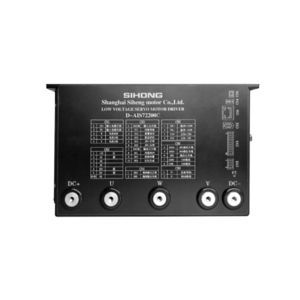
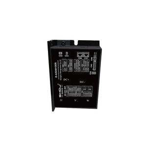
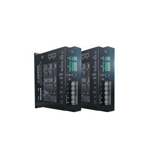
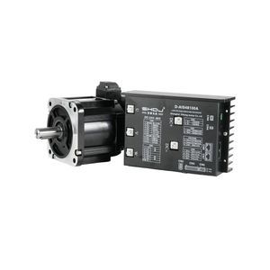
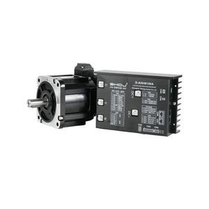
Сервовариатор DC D – AIS48025AModbusUSBдля ПК
Добавить в папку «Избранное»
Добавить к сравнению
Характеристики
- AC/DC
- DC
- Выходной сигнал
- USB, Modbus
- Применение изделия
- для управления, для позиционирования, для автобуса, для ПК, для тормоза, для приборов, для двигателя, двигатель
- Другие характеристики
- с контролем крутящего момента, умный
- Интенсивность
25 A
Описание
Product DetailsOverview:This product features strong stability, high-precision positioning, high motor response, low noise, low heat generation, excellent structural design, strong overload capacity, practical and rich functions, and simple and convenient application. It has protection against over-voltage, under-voltage, overspeed, overcurrent, overload, encoder failure, position deviation, stall, parameter deviation, etc.Technical SpecificationsDrive ModelVoltage Range (V)Rated Current (A)D – AIS24008A24 – 368D – AIS48015A24 – 4815D – AIS48025A24 – 6025D – AIS48050A24 – 7250D – AIS48100A36 – 72100D – AIS72200A48 – 96200D – AIS72300A48 – 96300Control Method① Position control ② Speed control ③ Torque control ④ Communication controlControl FeaturesSpeed frequency response: ≥200 Hz, Pulse input frequency ≤200 kHz, Speed change rate: < ±0.03 (Load 0 – 100%): < ±0.02×(0.9 – 1.1) Power supply voltageMonitoring FunctionCurrent speed, DI input, DO output, Current position, Command pulse input accumulation, Average load speed, Position deviation counter, Motor phase current, Bus voltage value, Module temperature, Alarm record, Command pulse frequency corresponding to speed, Operating status, etc.Home Return Function13 types of autonomous (search) home return modes, and home offset functionRS485 FunctionComplies with Modbus-RTU protocol, One-to-two communication interface for easy networking and parallel connectionDriver Installation DimensionsProduct Model: D – AIS48025ARated Voltage: 24 – 60VRated Current: 25ASplit-type Driver Hardware InterfaceApplicable drive models: D – AISXX005A / D – AISXX0015A / D – AISXX0025A / D – AISXX0040A / D – AISXX00100A / D – AISXX00200ASplit-type AI MOTOR Driver Interface DiagramSerial No.SymbolFunctionNotesCn11UMotor U-phase. Power cable JVW interface for motor adaptation.2VMotor V-phase3WMotor W-phase4DC–Negative pole of input power supply. External DC input must distinguish positive and negative poles; voltage range: 48V DC5DC+Positive pole of input power supply...(Further detailed pinout and wiring tables are available in the original description.)Reference Table for Selecting Discharge Brake Resistor for Split-type Driver Interface Cn9Split-type Drive ModelRated Output CurrentExternal Brake Resistor Resistance RequirementExternal Brake Resistor Power RequirementD – AISXX008A8A10 – 30 ΩOver 100WD – AISXX0015A15A10 – 30 ΩOver 100WD – AISXX0025A25A10 – 30 ΩOver 100WD – AISXX0050A50A5 – 15 ΩOver 200WD – AISXX00100A100A5 – 15 ΩOver 200WD – AISXX00200A200A5 – 15 ΩOver 200WStandard Wiring DiagramHigh-speed Pulse Signal WiringDI and DO Terminal WiringDO Output Terminal WiringRS485 Communication WiringMulti-slave ConnectionDebugging Connection with Host ComputerFor more detailed pinout, wiring, and technical notes, refer to the original tables and diagrams.Strong stability and high-precision positioningHigh motor response, low noise, low heatExcellent structural design and overload capacityRich monitoring and protection functionsMultiple control and communication methodsComprehensive wiring and installation options
Другие изделия Shanghai Siheng Motor Co., Ltd
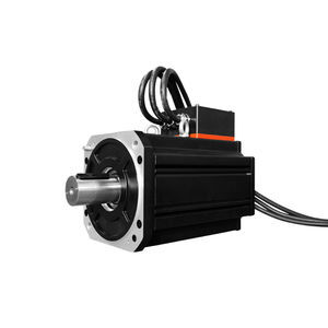
Split DC servo motor and driver
Расширенный поиск
- Двигатель для транспортного средства
- Двигатель с постоянным током
- Двигатель AC
- Синхронный двигатель
- Мотор-редуктор
- Промышленный двигатель
- Мотор-редуктор Постоянный ток
- Двигатель BLDC
- Двигатель 24 В
- Промышленный мотор-редуктор
- Концентричный мотор-редуктор
- Эпициклоидальный мотор-редуктор
- Сервовариатор
- Электрический серводвигатель
- Ортогональный мотор-редуктор
- Мотор-редуктор CA
- Шаговый двигатель
- Двигатель 220 В
- Серводвигатель AC
- Сервовариатор с постоянным током
* Цены указаны без учета налогов, без стоимости доставки, без учета таможенных пошлин и не включают в себя дополнительные расходы, связанные с установкой или вводом в эксплуатацию. Цены являются ориентировочными и могут меняться в зависимости от страны, цен на сырьевые товары и валютных курсов.


